Standing Rigging

Dyneema Grommets Looped Together to Form a Chain

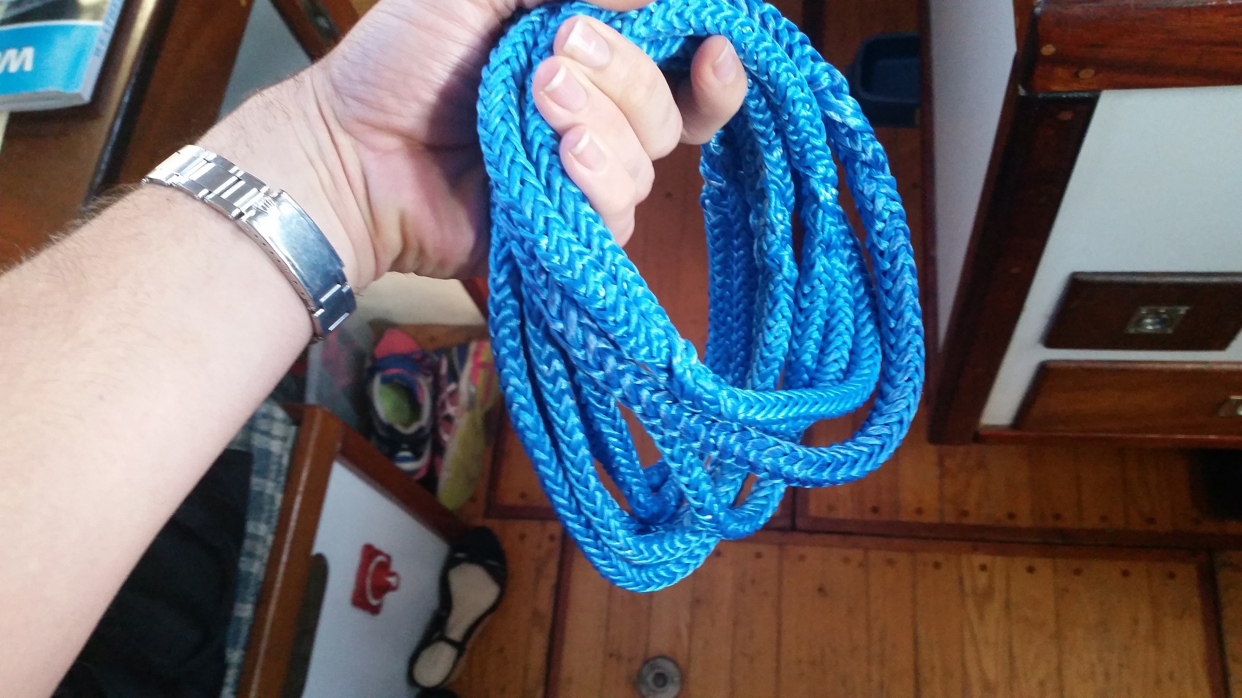
I was recently asked if the grommets could be tied in an interlocking fashion as to create a chain of dyneema links using my method of making a dyneema grommet.
The answer to this question is an obvious yes, each grommet simply needs to be spliced together with the previous grommet inside the loop.  

upload.jpg

I had actually made a set of three links while I was still practicing the art of making grommets to use as deadeyes. I made three links to quickly and easily evaluate the interaction between two pieces of dyneema under a load. 

The three links provided me with a wealth of information about how dyneema interacts with loads placed upon it and how it interacts with other dyneema rope under a similar load. It also helped me evaluate the best position to locate the splice on the loop. The top link has the splice in the bottom at the connection to the middle link. The middle link has the splice in the middle. The bottom link has the splice located inside the thimble.

This information led to my decision on using thimbles in my deadeyes and to position the splice in the middle of the deadeye. The top link was hooked over a pipe on a scaffold where the middle link connected the system to the bottom link which had a weight hanging from it. I didn't take any pictures of this test because I didn't have a website or any plans on doing rigging commercially at that time. I was merely designing and testing methods to re-rig my own yacht which led me to produce the current system that I have and use.

The results of the test can still be seen in the loops though. The top link (left link in the photos) was hooked over the scaffold and still retains the bend that it picked up while under the load. The bottom link had a thimble in the bottom portion to hold the weight. The middle link was left untouched to evaluate how the different connections interact.

The top link that was hooked over the pipe was fine, indicating to me that if the object I am attaching to is large enough, the grommet can simply loop over it without any other form of connector.

upload.jpg

The junction of the top link to the middle link also tested the durability of the splice when under direct contact by other ropes. The splice held up fine, even though the middle link formed a tight radius bend over the splice.

upload.jpg

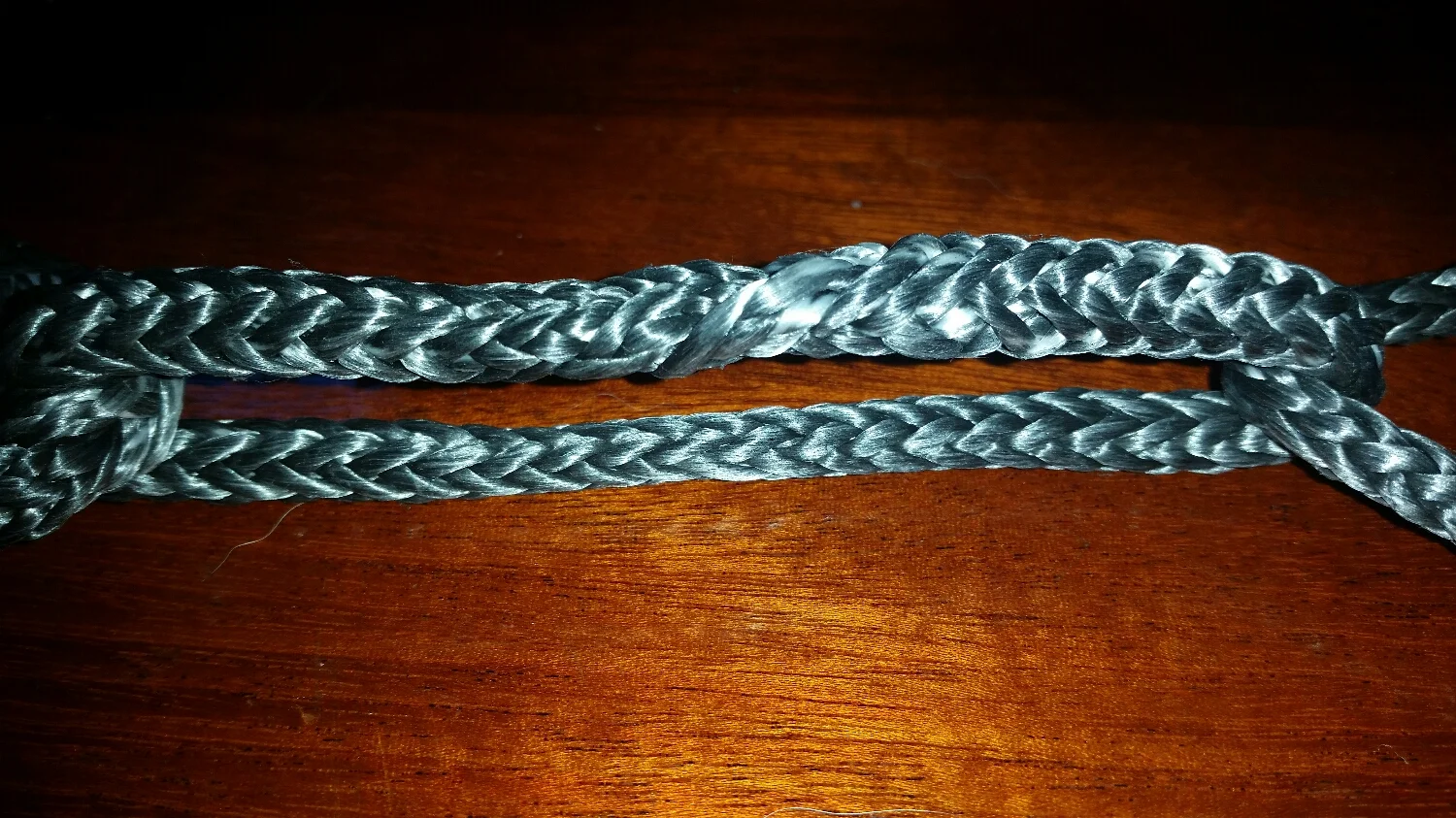
The middle link was the most interesting to observe. It has tight radius bends at either end and the splice located in the middle of the link. The splice side and the bury side both shared the loads equally and evenly. The splice was also easier to inspect which became my preferred position to locate the splice for the deadeyes. The ends of the middle link did suffer from being bent over the tight radius turns of the other links, which could lead to reduced longevity of the grommet. The deadeyes for the standing rigging should not be subjected to such tight radius turns as it could lead to premature failure of the dyneema.

upload.jpg

The connection of the middle link to the bottom link is different from the connection at the other side of the middle link, where a splice was involved. This connection was simply two pieces of dyneema bending over each other. They seemed to hold up well, but did form a rather tight radius bend, which is not the best for longevity of the dyneema.

upload.jpg

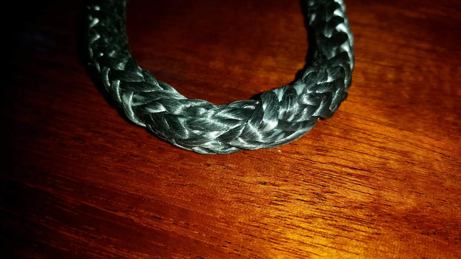
The end of the bottom link was subjected to loads with a thimble placed in it. The splice was also located at the bottom, inside the thimble. The splice held find under load and with a large radius turn, as guided by the thimble used. This seemed to be the preferred way to connect the standing rigging to the deadeyes, as the thimbles will force the grommet to retain a properly radiused turn while under tremendous loads. The splice located at the bottom worked well but was difficult to inspect.

upload.jpg

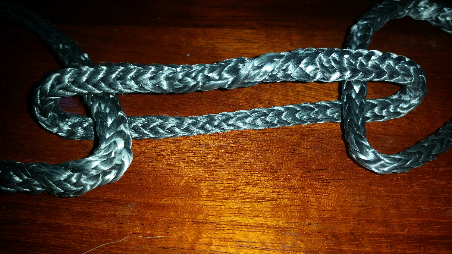
After being loaded, the links retained the shapes they became during the test. The top and bottom links had ends that were forced to maintain large radius bends due to the scaffold pipe on the top link and the thimble on the bottom link. The ends that were not guided formed much tighter radius turns, as they folded over each other. While the bend was rather tight, the loads were maintained even on the links, and none of them showed any signs of problems. The splices also functioned well in all three locations: In the connection, in the middle, in the thimble; and the location for them to be in the middle on my deadeyes was purely for inspection purposes.

Based on this experiment, I decided to manufacture the deadeyes with thimbles on their ends and the splices located in the middle of the grommet. The thimbles provide a properly radiused bend even when under the immense load of working standing rigging.

Islander 36 Conversion: Making the Deadeyes

Once the length of the stays has been measured, manufacturing of the synthetic rigging can begin! The total length of the stay is a combination of all the components involved. 

At the top of the shroud, you will have the mast attachment components, and at the bottom of the stay, you will have a system for tensioning the stay. The length of all of these components needs to be subtracted from the length of the shroud to tell you how long your synthetic stay needs to be from eye splice to eye splice.

Before you can make the eye splices in your stay, you need to know exactly how long all of these components are, meaning you need to assemble everything before you can put the eye splices in the stays. 

The first step will be to manufacture the deadeyes. Each deadeye consumes four feet of line and is a bit of a tedious process. It is important to make all the deadeyes first, before you start making the stays. Having the finished deadeyes will let you measure the entire ends of the shroud and calculate how long the stay needs to be.

For the Islander 36, we will need to make one deadeye for the backstay and eight deadeyes for the shrouds, since it is a double spreader rig. This means that nine deadeyes in total must be manufactured. 


These dyneema loops are called grommets. They are made by creating a mobius brummel splice in the line, connecting the two ends together in a way that they can not slide open under pressure. The splice actually locks the two ends together in a fair and low stress method with the tails buried within the length of the grommet. 

The lot of these grommets took me just under seven hours to make, and it was a very tedious process. The next step will be to insert the stainless steel thimbles and tie a seizing knot in the middle to hold everything together. For more details on how to make a dyneema deadeye, check out the link below.

I didn't service the ends of these deadeyes like I did when I made my first set because the service is completely unnecessary. My thought process when I made the first ones was that the lashings might chafe the fibers of the deadeye as they run by it. The reality is the lashings do not chafe on the deadeyes because they are led by the thimble and never contact the deadeye. Secondly, as the deadeye creeps into place, the bluk of the deadeye thins and the service become loose on the deadeye and begins to unravel. Servicing the ends of the deadeyes took more than an hour per deadeye and was completely unnecessary. While it did add a splash of contrasting color to the deadeye, it ends up being a rather expensive feature that offers no additional benefit to the deadeye. If it is requested, the ends of the deadeye can be serviced with whipping twine, but it will add considerably to the labor time involved in manufacturing the synthetic standing rigging.

Converting an Islander 36 to Synthetic Standing Rigging

I am now working on an Islander 36. The port and starboard cap shroud and Intermediate chainplates have been replaced with new chainplates that I fabricated out of 316L stainless steel. 316L is the ideal form of stainless steel for chainplates. The "L" stands for "low carbon" which gives the metal more resistance to crevice corrosion. 

The cap shrouds and intermediate shrouds connect to the same chainplate, and since the port chainplate had fractured and come through the deck, it wasn't safe to climb the mast until these new chainplates were installed and connected to the old rigging. 

Once everything is setup and stable, we can go ahead and measure the rigging with the mast in its current position. The measurements are then taken to calculate how much dyneema we need to complete the re-rig. 

When you order your line, be sure to add in the amount of line that will be consumed by splicing. In our case, we are using 7mm New England Ropes STS-HSR for the backstay, and 6mm New England Ropes STS-HSR for the shrouds. The headstay will be replaced with 316 Stainless Steel 1x19 wire so that the owner can retain his roller furling headsail. 

The amount buried in a splice is 72 times the diameter of the rope. For 7mm line,  that's 504mm or 20.1 inches per splice. This means that each stay needs an additional 20 inches on each end, ordering a few extra inches is advisable as it is always easier to cut off a few extra inches than to fix coming up a few inches short!

The deadeyes will consume 4 feet of rope each, and each stay needs one to connect it to the chainplate. There are 2 cap shrouds, 2 intermediate shrouds, 4 lower shrouds, and 1 backstay to replace with synthetics. 

Once the total amount of line is known, an order can be placed and fabrication can begin once it arrives!

Synthetic Rigging Tensioning System

The setup to tune synthetic rigging with deadeyes is very simple, all you need is a turning block, and some leads that can be run to a winch. This allows you to use achieve the necessary tension in the stays in a controlled and repeatable manner.

To begin, the turning block is tied to the toe rail where a fair lead is in plane with the deadeye. This will ensure that the force on the lashings is vertical with no horizontal component.

Once the turning block is positioned properly, untie the tails and lead them through the turning block, then over to the tensioning line. The tensioning line (9mm VPC) is led to the winches in the cockpit. I use the secondary winch for the anchor and the primary winch to drive the tension. To connect the tails to the VPC tensioning line, I use a sheet bend with a slip; this knot will hold securely as incredible loads are applied to the system, but is also possible to untie after the procedure is completed.

One important trick when tensioning the stay is to set everything up as seen in the photo above, then apply tension to the whole system before untying the shroud frapping knot. This will make sure the tensions are similar between the tails and lashings once the shroud frapping knot is untied. 

Once the shroud frapping knot is untied, tension can be added to the stay via the cockpit winches until the appropriate amount of tension is present in the stay. I perform this adjustment on both sides of the boat at the same time to ensure that the mast stays in column and that the stays are of similar tension. This does require double the setup materials, but the end result is very even tensioning of the standing rigging.

For more details into how to tension your synthetic standing rigging with deadeyes, please read this post.

Chainplate Fabrication: Part 3

To properly radius the holes of the chainplate, I use a carbide bur in a high speed hand piece followed up with an abrasive cone in a low speed hand piece.

These burs will result in a smooth and rounded transition from hole to chainplate, reducing the risk of point loading on the fasteners near the corners.

With lots of water flowing over the work site, I am able to keep the whole system cool while rounding up the corners. After the course reduction was completed, finer polish was achieved with the slow speed hand piece, smoothing it all up. This step could also be completed using a dremel tool, but as a dentist, a drill is second nature and I know I can get the exact result that I need!

Now the chainplates are finished and ready to be installed with new hardware and beeded into the deck to seal out any water intrusion.